Making use of an old IBM terminal keyboard
2025-02-05Arduino, ATtiny, electronics, retro
I've found two magnificient IBM 3488 keyboard in the street, the kind that makes a clicky sound when you press a key.
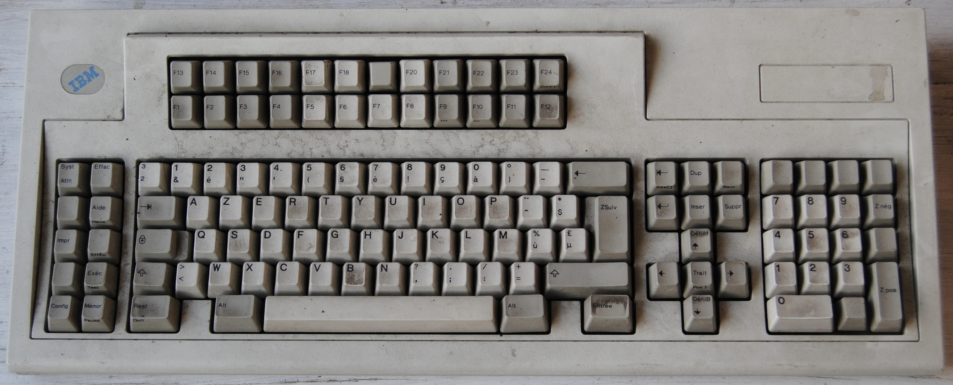
Unfortunately, the cables have been cut so I don't know what the interface is. No, it's not PS/2. This model is designed to work with a Twinax terminal, not with a computer, and it's using a proprietary IBM protocol.
#Figure out the protocol
First, we see the 5-pin connector we want to interface with.
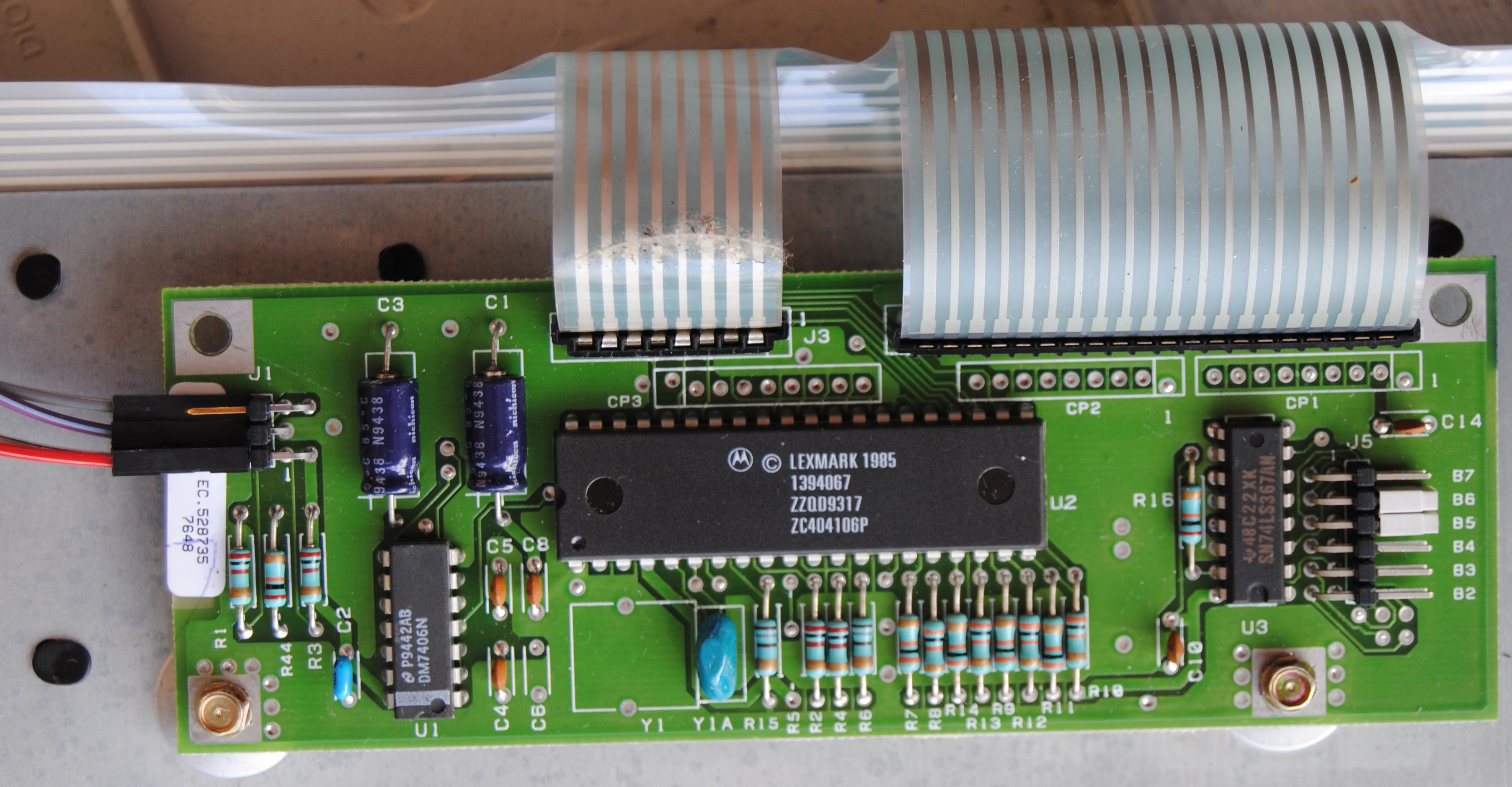
Good thing, these two little ICs (DM7406N, SN74LS367AN) have a datasheet online and work at 5V, so we can identify voltage, GND and VCC.
How to get any idea about what each of the three other pins do? Let's start by monitoring their activity with an Arduino Mega:
volatile unsigned long changes[3][64];
volatile unsigned long changes_n[3];
volatile unsigned long last_change;

void isr(unsigned int i) {
  unsigned long t = micros();
  last_change = t;
  changes[i][changes_n[i]] = t;
  changes_n[i] = (changes_n[i] + 1) % 64;
}

void isr0() { isr(0); }
void isr1() { isr(1); }
void isr2() { isr(2); }

void setup() {
  Serial.begin(115200);
  pinMode(2, INPUT); // On Arduino Mega, interrupts are allowed on these pins
  pinMode(3, INPUT);
  pinMode(18, INPUT);
  attachInterrupt(digitalPinToInterrupt(2), isr0, CHANGE);
  attachInterrupt(digitalPinToInterrupt(3), isr1, CHANGE);
  attachInterrupt(digitalPinToInterrupt(18), isr2, CHANGE);
}

void loop() {
  if(
    micros() > last_change+100000
    && (changes_n[0] > 0 || changes_n[1] > 0 || changes_n[2] > 0)
  ) {
    for(unsigned int i = 0; i < 3; i ++) {
      for(unsigned int j = 0; j < changes_n[i]; j ++) {
        Serial.print(i);
        Serial.print('\t');
        Serial.println(changes[i][j]);
      }
      changes_n[i] = 0;
    }
  }
}
This program records the time of each change on each of the three pins, then sends it to the computer.
Result when pressing a key:
0	11916736
0	11916776
0	11916824
0	11916864
0	11916908
0	11916948
0	11917000
0	11917032
0	11917084
0	11917116
0	11917168
0	11917204
0	11917248
0	11917288
0	11917336
0	11917376
0	11917416
0	11917460
0	11917500
0	11917540
0	11917588
0	11917620
1	11916756
1	11916796
1	11916840
1	11916880
1	11916924
1	11916964
1	11917016
1	11917048
1	11917100
1	11917136
1	11917184
1	11917220
1	11917264
1	11917304
1	11917356
1	11917392
1	11917436
1	11917476
1	11917516
1	11917556
1	11917604
1	11917640
2	11916720
2	11916980
2	11917064
2	11917152
2	11917320
2	11917572
We can guess that 0 and 1 are clocks, and 2 is data. Pin 0 changes every 40µs, while pin 2 has a minimum period of about 80µs, so a data bit should be triggered by pin 0 falling xor rising.
Knowing that, we can try to decode the data:
#define PIN_CLOCK 2
#define PIN_DATA 18
#define BUF_LEN 64

volatile unsigned int rec = 0;
volatile unsigned int offset = 0;
volatile unsigned char buf[BUF_LEN];
volatile unsigned int n;

void isr() {
  unsigned int d = digitalRead(PIN_DATA);
  if(offset == 0 && d != 0)
    return;
  rec |= d << offset;
  offset ++;
  if(offset >= 11) {
    offset = 0;
    if(rec != 0) {
      buf[n] = rec >> 1;
      rec = 0;
    }
    n = (n + 1) % BUF_LEN;
  }
}

void setup() {
  Serial.begin(115200);
  pinMode(PIN_CLOCK, INPUT);
  pinMode(PIN_DATA, INPUT);
  attachInterrupt(digitalPinToInterrupt(PIN_CLOCK), isr, FALLING);
}

void loop() {
  if(n > 0) {
    for(unsigned int i = 0; i < n; i ++) {
      Serial.println((unsigned int) buf[i]);
    }
    n = 0;
  }
}
I first tried 8 bits of data, but then multiple presses of the same key gave seemingly random numbers. Not random in fact, they were periodical. So I tried other numbers until having reliable results, and 11 is the right number of bits.
It also appears that the bits 1 and 2048 are always clear, and that the bit 1024 is always set. So it remains 8 bits of true data, perfect!
#Design an adapter
Most microcontrolers don't have a USB interface, and that can't be emulated by software. However we can easily emulate PS/2 with bit-banging.
Luckily I have a lot of ATtiny402. They are SOIC-8 chips with 5 GPIO that can be programmed using the Arduino IDE. Let's use this!

Warning: I don't know whether it is safe to connect USB's and PS/2's +5V together. It probably depends on the motherboard. Just in case, never power the Arduino simultaneously from both.
#PS/2 emulator
The Arduino library ps2dev works well for PS/2 device emulation. The problem is that the program size is too big (4414 bytes when compiling to Arduino Mega which I'm using for the prototype), even without some important features like special keys and a proper press/release handling. Is that big, really? Well, Attiny402 has 4kB of programmable memory and 256B of SRAM. I had to optimize bytes almost one by one:
- Replace the C++ class (which is instanciated only once) with functions and globals: big improvement ^^
- Replace the standard
delaywith a custom implementation usingmillis: big improvement :p - Replace
intwithchar: each gave 20 to 50 bytes O_o - Remove ifs (using operators and bit-fiddling): a few dozens of bytes each :)
- Factor some code: a few bytes x_x
- Inline some functions: a few bytes :3
- Remove features (LED): dozens of bytes (the IBM keyboard has no LED anyway)
It eventually dropped down to 3708 bytes. Small enough for the Attiny!
#Programming the ATtiny
The Arduino IDE does not support ATtiny out-of-the-box. Instead you have to install megaTinyCore that supports lots of ATmega and ATtiny chips. If you read its README (and you really have to, if you want to use it), you understand that the Arduino IDE and AVRdude are built on a pile of obsolete code and that the world of microcontrolers is dark magic everywhere. After reading all this documentation (or story), flashing a chip with AVRdude feels like making a sacrifice to the Gods of Randomness and Technical Debt.
And of course, megaTinyCore no longer works on my system, for obscure reasons (undocumented behaviors and cryptic error messages of the Arduino IDE).
When I finally got the courage to uninstall the Debian-packaged Arduino IDE and install the upstream 1.8.13 (as advised by megaTinyCore's doc), it worked. The program size then dropped to 2367 bytes! (Is the Arduino core library that badly written?) Maybe my optimizations weren't necessary after all... >_<
Here is the wiring for the ATtiny:
| ATtiny | Arduino | Keyboard | PS/2 |
|---|---|---|---|
| VCC | VCC | VCC | +5V |
| GND | GND | GND | GND |
| UPDI | 6 or 18 | ||
| PA1 | Clock | ||
| PA2 | Data | ||
| PA6 | Clock | ||
| PA7 | Data |
Note about UPDI: For Arduino Mega, use pin 18. For any other board, use pin 6. This pin is used for programming only but I like to leave an accessible header so I can reprogram the chip later.
Don't forget the 100nF capacitor as close as possible to the ATtiny's power pins.
Open jtag2updi in the Arduino IDE and upload it to your Arduino board. This allows the Arduino to act as a bridge between the computer and the ATtiny.
Now open the ibm-ps2-keyboard sketch and set the following settings:
- Board: megaTinyCore/ATtiny402
- Chip: ATtiny402
- Clock: 20MHz internal
- Other settings: leave default
- Programmer: jtag2updi (it appears only when the board is selected)
Do NOT use Burn Bootloader or Upload Using Programmer! Just use the normal upload button.
If you have errors like avrdude: jtagmkII_getsync(): sign-on command: status -1, then press the Reset button on the Arduino and it should work.
#Make the circuit
Such a simple circuit can easily be made at home, with minimal tooling.
As there are good tutorials for this on the Internet, I'll just very quickly show each step.


I use acrylic paint for masking, applied with an thick olive stick.

Wait a few hours to let it dry, then scratch the excess paint with a sharp tool. Be very gentle or it will strip off the entire paint blob. You want to scratch the paint, not to cut it.

Put the plates into a ferric chloride solution. Always use protective gloves and goggles, and do this outside or aerate. Never use metallic tools, they will react with the acid.

Do not dispose of used ferric chloride anywhere: it will corrode the pipes and pollute. The same solution can be re-used a few times.
Oops, there are copper bridges, I still have to remove them with a rotative tool.


Ok, my soldering is really dirty, but hey, it works!